Informazioni relative al progetto
Client
Prelios SRG S.p.A.
TYPE OF INTERVENTION
Refurbishment
LOCATION
Via Veneto 89, Roma
DURATION
Project: 2019 – 2022
Construction: 2022 – 2024
SERVICES
- Preliminary MEP Design
- Detailed MEP Design in BIM
- Construction MEP Design in BIM
- MEP Works Supervision
- APE Energy Certification
- LEED Certification Consultancy
- WELL Certification Consultancy
- BREEAM Certification Consultancy

MEP WORKS VALUE
|
Total: |
10.910.289,07 € |
 Breeam
 Leed Platinum
 Well
WellDescription
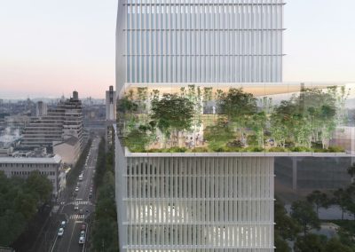
The Veneto 89 building, located in the heart of Rome’s historic centre, enjoys a prime location just a short walk from some of the city’s most iconic landmarks, such as Piazza Barberini, Piazza di Spagna and Villa Borghese. It represents an emblematic example of the classical architecture of 20th-century Roman palazzi.
The new Veneto 89 project is conceived as a contemporary reinterpretation of office spaces, with some ground-floor areas dedicated to retail use. While respecting the monumentality originally envisioned by architect Carlo Broggi for the former INA building, the new configuration preserves its external role and identity while enhancing internal usability and liveability, maintaining high accessibility standards in line with the needs of contemporary work environments.
The redevelopment project, in addition to preserving the building’s original intended use, includes the restoration of its typological and formal characteristics as well as a significant improvement in energy performance, in full compliance with current regulations and with the aim of making the property highly efficient.
Environmental sustainability played a central role throughout the entire design process, involving the different teams from the earliest stages through to the full completion of the works, in compliance with the requirements of the LEED v4 BD+C: C&S protocol.
The intervention consists of a major refurbishment aimed not only at renewing the internal spaces, but above all at improving energy performance and indoor comfort. This result was achieved through targeted measures both on the building envelope, by replacing the existing windows with more efficient solutions, and on the building services systems, through the adoption of high-efficiency mechanical and electrical systems, thereby reducing the overall energy consumption. Consumption can also be periodically monitored through supervision systems connected to the building BMS.
It should also be noted that the building’s entire electricity supply is green, coming 100% from renewable sources, which is now a fundamental choice from both an environmental and energy perspective.
Particular attention was paid to the well-being and comfort of occupants through the installation of a high-efficiency air-conditioning system. The HVAC system consists of two air-source multifunction units combined with six AHUs, each dedicated to supplying outside air to specific areas of the building.
To reduce water consumption, low-flow fixtures were selected. In addition, thanks to the use of LED lighting fixtures and the careful design of the external lighting, it was possible to further reduce the building’s overall energy consumption and minimise light pollution.
Sustainable site management also played a key role in reducing environmental impacts during all construction phases. To meet the requirements of the LEED protocol, preference was given to the installation of recycled materials, with appropriate environmental certifications and low or zero VOC content.
Mechanical Systems
The design of the systems, particularly those intended for air conditioning and domestic hot water production, was aimed at reducing energy consumption without compromising indoor comfort and system reliability. To achieve this objective, efficient technologies and renewable sources were adopted, in particular the use of groundwater for heating and cooling production, considered a renewable source.
The selected system solutions include high-efficiency heat pumps, heat recovery systems and devices capable of adapting operation to the actual instantaneous needs of the spaces by regulating the flow rate of the thermal carrier fluids. Modulating pump speed in fact allows significant energy savings, since the absorbed power decreases more than proportionally compared to the reduction in flow rate.
Heating and cooling generation is entrusted to two water-source multifunction units using groundwater as a geothermal source. Water is drawn through four extraction wells, from which it is conveyed to plate heat exchangers protected by industrial self-cleaning filters rated at 200 microns, installed in the technical plant room on the basement level. The system is controlled by temperature probes and variable-speed pumps in order to ensure correct operation according to thermal demand.
Once used, the water is returned through five discharge wells, in compliance with the regulatory limit of a maximum temperature of 21°C. The entire geothermal network is made of high-density polyethylene (HDPE PN16).
The hydronic circuits are distributed so as to separately supply:
- the AHU cooling coils (8/14°C);
- the fan coils and heat recovery units in cooling mode (10/15°C);
- the AHU heating coils (40/35°C);
- the fan coils and recovery units in heating mode (40/35°C).
Each circuit is equipped with the necessary expansion and make-up components, as well as shut-off valves and 6-way PIBCV valves capable of dynamically managing both balancing and control. Differential bypass valves ensure the minimum circulation required during partial-load periods.
Pipes passing through building structures are adequately protected by galvanized sheet metal sleeves and fire-stopping seals where required.
The building предусматривает mixed air/water systems for all areas with continuous occupancy, with functional zoning based on the use of the spaces.
The hotel rooms are served by ceiling-concealed AHUs with heat recovery, integrated with 4-pipe ducted fan coils positioned near the entrance. Primary air is supplied into the fan coil plenum, while return air is extracted through grilles located in the bathroom. The terminal units are selected for low-speed operation in order to minimise acoustic impact. Each bathroom is also equipped with a heated towel rail.
The common areas, such as the lobby and restaurant, also use mixed systems, with dedicated AHUs and ceiling-mounted fan coils. For architectural reasons, some sections, such as the mezzanine floor, feature fully exposed systems.
The basement rooms intended for offices, gym and kitchenette are equipped with ceiling-mounted heat recovery units and cabinet fan coils. The system design took into account the limited available heights, which is why some sections of the systems are also exposed in these areas.
The kitchen is served by two units: one 100% outside-air AHU with heating/cooling coils and a second unit for direct supply into the compensated hood, integrated with the extraction system.
Plumbing and Sanitary Systems
The building is supplied from the public water network, with distribution through a break tank system and pressure boosting unit. Water intended for domestic hot water production is softened, stored in calorifiers with stainless steel plate heat exchangers and treated against legionella.
DHW production is entrusted to geothermal heat pumps, with storage at 65°C and distribution at 55°C through a mixing valve. Additional mixing valves are installed at the entrance to the bathrooms in order to avoid the risk of scalding.
Water is distributed through insulated galvanized steel pipes up to the manifolds and, from these, through insulated multilayer pipes to the sanitary fixtures. Each service block is equipped with shut-off valves. Penetrations through structures are made with metal sleeves and, where required, with adequate fire protection systems.
Water distribution within the bathroom blocks is carried out through multilayer pipes in series configuration. Each bathroom is equipped with a thermostatic mixing valve to protect user safety.
Irrigation is fed from a rainwater collection tank, supplemented by groundwater coming from the air-conditioning circuit. Distribution is ensured by submersible pumps.
The rainwater drainage system is sized in accordance with UNI EN 12056-3. Water is collected in a 50 m³ first-flush tank, also intended for LEED objectives, and, in the event of overflow, in a second 135 m³ attenuation tank. The latter regulates discharge into the sewer system, in compliance with Lombardy regional regulations on hydraulic invariance.
Condensate from the AHUs and technical rooms is collected and pumped into the sewer system by lifting stations, while fan coil condensate is conveyed to the nearest drains. Each AHU is equipped with a trap and the technical rooms with trapped floor drains.
Black water networks collect discharges from bathrooms and plant rooms. For these networks, soundproof polyethylene or additive-enhanced polypropylene pipes were used. The stacks are vented up to roof level. Black water from kitchens is treated by means of a grease separator.
Inspection points and penetrations protected by fire protection systems are also provided. For acoustic control, rigid fixings are avoided and anti-vibration collars and damping materials are used.
Fire Protection Systems
The building’s fire protection is ensured by a water-based system consisting of a hydrant network. The core of the system is the fire pump station, sized in accordance with current technical regulations, which feeds the building’s fire water networks.
The station consists of two preassembled units compliant with UNI EN 12845, installed in flooded suction configuration. Each unit includes one main electric pump, one standby diesel pump and one jockey pump, required to maintain constant pressure within the networks.
A main manifold starts from the station, from which three lines branch off: one for the internal hydrant network, one for the external hydrant located in the courtyard, and one dedicated to the fire brigade pump connection. The pipes are made of galvanized steel and painted RAL 3000, the typical colour for fire protection systems, to ensure durability and immediate recognisability.
The risers, positioned in protected filter areas, distribute water to the various floors of the building, where the horizontal networks develop towards the recessed wall hydrants.
The system is completed by portable or wheeled extinguishers, either powder or CO₂ type, distributed throughout the different areas in accordance with the fire prevention design.
Pressurization Systems for Smoke-Proof Lobbies
The smoke-proof lobby pressurization system consists of a self-powered unit managed by a control panel. In the event of fire, detected either by sensors or by manual commands, the system activates and guarantees an overpressure of at least 0.30 mbar for more than 2 hours, even in the absence of power thanks to the presence of storage batteries.
The control panel indicates system status by means of LEDs and a buzzer. If doors are not properly closed, a pre-alarm is activated, which becomes an alarm if the condition persists, causing the emergency unit to intervene. The system can be activated either manually or automatically via sensors or push buttons.
Control and Regulation System
An integrated automation and supervision system is provided for the technological systems, environmental control and management, and special safety systems, with the aim of ensuring optimised operation of the entire complex.
The system is integrated with the room management system envisaged in the electrical design and is interfaced with the technological systems to be controlled according to the indicated battery limits and the solutions adopted by the suppliers of the various systems and equipment.
The system essentially includes:
- integrated supervision of all systems;
- control of the mechanical systems;
- custom software programs;
- training of the Client’s staff.
Electrical System
The design follows the current technical regulations, in particular CEI standards, and every part of the system is designed to ensure safety, reliability and compliance with the required performance levels.
The earthing system is intended to protect people and equipment in the event of electrical faults. It includes the installation of an earth electrode network consisting of copper conductors and rods connected to the reinforcement bars of the reinforced concrete structures. All electrical switchboards are connected to a central equipotential node, from which the connections branch out to the various devices.
The lightning protection system is designed in accordance with CEI EN 62305 standards and is intended to protect the structure against direct or indirect lightning strikes. The system includes air terminals, down conductors and the earthing system.
Several low-voltage switchboards are envisaged:
- QGBT-SC: for common services;
- QGBT-ALB: for the hotel;
- QGBT-RIS: for the restaurant;
- QGBT-SKPI: for the skybar and swimming pool.
Each switchboard has been designed according to criteria of modularity, selectivity and safety, with circuit breakers, disconnectors and overload and short-circuit protection systems.
On the various floors of the building and for each specific function, such as lifts, the heating/cooling plant room and hotel rooms, secondary electrical switchboards are provided. These manage local power distribution and are designed to integrate with the BMS supervision and automation system.
Lighting of the common areas follows LEED criteria for energy efficiency. All rooms are equipped with lighting systems compliant with the minimum illuminance levels required by the standards, including stairwells, guest rooms, restaurant, skybar and swimming pool.
Power supply to the mechanical, technological and socket outlet systems is guaranteed by a dedicated power distribution system. The lines are divided into primary and secondary, with risers and mains sized according to the required loads.
The electrical energy distribution is organised as a capillary network connecting the main switchboards to the secondary ones through risers and mains. The lines are installed by cable, either concealed or on cable trays, with sizing calculated to avoid excessive voltage drops.
PROJECT DESCRIPTION
xxxxxxxxxx